Vacuum Force Explained: How to Measure Vacuum Suction

Understanding how to measure vacuum suction is crucial for anyone working with pneumatic lifting devices, automation systems, or vacuum-based handling equipment. Measuring vacuum suction accurately helps ensure that the applied force is strong enough to lift, hold, or move objects safely and efficiently. In this article, we’ll break down the science behind vacuum force, explain the tools and methods used to measure it, and show how proper measurement can enhance performance, safety, and reliability in your lifting applications.
Understanding Vacuum Force
Vacuum force is the gripping or lifting force created when a suction cup or vacuum system holds an object. It works by creating a pressure difference between the inside of the suction cup (low pressure) and the surrounding atmosphere (higher pressure). This difference causes the atmospheric pressure to push the object toward the suction cup, securely holding or lifting it.
Key Points:
- Atmosphere “pushes,” not the vacuum “pulls”: The force comes from higher external air pressure pressing the object into the low-pressure zone.
- Suction force depends on:
- Pressure difference (ΔP) between the vacuum and the atmosphere
- Contact area of the suction cup (larger area = stronger hold)
- Formula:
F=P×AF = P \times AF=P×A
where:
F = suction force, P = pressure difference, A = contact area.
Why It Matters
- Ensures the vacuum system can lift or hold the object safely.
- Prevents slipping or dropping of the load.
- Avoids wasting energy or damaging delicate materials by using excessive vacuum.
By understanding vacuum force, you can design and operate vacuum lifting systems that are safe, reliable, and efficient.
Working Principle: How Vacuum Suction Works
Vacuum suction works by using differences in air pressure to hold objects securely without mechanical clamps. Here’s a step-by-step explanation:
- Contact & Seal
The suction cup is positioned on the object to create a tight seal. A proper seal is important because any small leaks can weaken the vacuum, reduce holding force, and may cause the object to slip. - Air Evacuation
Air is drawn out from inside the sealed suction cup using a vacuum generator, pump, or ejector. Removing the air creates a low-pressure zone inside the cup, which is essential for generating the suction force that holds the object securely. - Pressure Difference Creation
As air is removed from the suction cup, the pressure inside drops below the outside atmospheric pressure. This pressure difference generates a force that presses the cup firmly against the object. The object is not being pulled upward; instead, it is held securely by the higher air pressure surrounding the cup. - Holding Force Established
When a stable pressure difference is achieved, the suction cup securely holds the object in place. This allows it to be lifted, rotated, or moved safely without slipping. The even and controlled grip makes vacuum suction ideal for precise, non-damaging handling of delicate or sensitive items.
See also: Ways Smart Traffic Technology is Revolutionizing Transportation with SINTRONES and NVIDIA
Supporting Forces: Gravity and Friction
- Gravity: Atmospheric pressure exists because of Earth’s gravity. This pressure is what “pushes” the object against the suction cup.
- Friction: The contact between the cup and object adds stability. Smooth surfaces rely mainly on the vacuum, while rough or oily surfaces benefit from friction to prevent sliding.
This principle makes vacuum suction ideal for industries requiring precise, safe, and delicate handling of materials.
Tools for Measuring Vacuum Suction
Vacuum suction systems rely on accurate tools to measure and monitor pressure. Here’s a clear overview of the main instruments used:
- Vacuum Pressure Gauges (Dial or Analog)
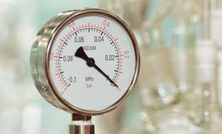
These gauges display vacuum levels on a dial, typically in units like mbar, inHg, or mmHg. They are often mounted directly on suction lines, vacuum pumps, or manifolds to give real-time vacuum pressure readings.
- Pros: Simple, durable, easy to read, and good for quick visual checks.
- Cons: Less precise, slower to respond, and not ideal for fast-changing or highly accurate measurements.
Best for: Routine checks or non-critical systems.
- Digital Vacuum Gauges / Sensors / Transducers
These electronic devices show vacuum readings as digital numbers and often provide electrical signals for data logging or automation systems.
They work using advanced sensors to detect pressure differences.
- Pros: High accuracy, fast response, ideal for monitoring and automated control.
- Cons: More expensive, require calibration, and are sensitive to installation or environmental conditions.
Best for: Precision applications or automated production systems.
- Manometers (U-Tube or Inclined Types)
These traditional tools are used to measure pressure or vacuum. They work by showing how much a liquid moves inside a clear tube when pressure changes.
- Pros: Very simple and reliable for reference or calibration use.
- Cons: Bulky, slower response, and not practical for everyday industrial use.
Best for: Laboratory calibration or training setups.
- Calibration and Reference Tools
Calibration and reference tools are used to ensure that vacuum gauges and sensors provide accurate readings. They are not typically used for daily operation but are essential for maintaining measurement reliability.
What to Consider When Choosing a Tool
- Range & Resolution: Match the tool to your vacuum level (e.g., −0.2 bar for light vacuum, −0.8 bar for strong vacuum).
- Response Time: Use faster digital sensors for rapid pick-and-place or dynamic suction.
- Installation Location: Mount the gauge near the suction cup to minimize measurement errors.
- Output Needs: Choose digital sensors if you need data logging or system integration.
- Calibration: Regular calibration maintains measurement accuracy and safety.
- Environment: Ensure the tool can handle your operating temperature, vibration, and dust conditions.
Step-by-Step Measurement Procedure
- Prepare the System
Ensure the vacuum source (pump or ejector) is clean and working properly, and check all hoses, fittings, and valves for leaks. This ensures the system operates safely and that vacuum measurements are accurate.
- Connect the Vacuum Gauge or Sensor
Attach a vacuum gauge or sensor using proper fittings and airtight seals. Place it as close as possible to the suction cup or interface to get accurate and reliable vacuum readings.
- Activate the Vacuum System
Turn on the vacuum pump or ejector and allow the system to reach a steady-state vacuum before taking any measurements.
- Record Vacuum Levels
Measure the vacuum pressure both with the suction cup empty (no-load) and while holding the object (load). This ensures the system provides enough suction for safe and effective handling.
- Verify Holding Force
Use the measured vacuum level and the suction cup’s contact area to calculate the holding force. Ensure this force is enough to safely lift and hold the object based on its weight and surface type.
Holding Force Calculation: What to Consider
Calculating the holding force is key to choosing the right suction cup. To do it correctly, you need to account for the workpiece properties, system dynamics, and safety factors.
A. Workpiece Properties
- Material Type: Steel, glass, wood, plastic, etc.
- Surface Condition: Smooth, rough, curved, porous, or oily surfaces affect how well the suction cup seals and the friction it can generate.
- Mass: Calculate the object’s mass using:
m=ρ×Vm = \rho \times Vm=ρ×V
Where:- mmm = mass (kg)
- ρ\rhoρ = material density (kg/m³)
- VVV = volume (m³)
This helps determine the suction force needed to lift or hold the object.
B. Dynamic Factors
- System Acceleration (a): How fast the object moves (m/s²).
- Gravity (g): Standard 9.81 m/s².
The combination of gravity and acceleration determines the real-time force the suction cup must resist.
C. Additional Parameters
- Safety Factor (S): Adds a margin to prevent slippage or accidents. Typical values:
- Smooth surfaces: 2–3
- Rough or oily surfaces: 3–5
- Vertical lifts or porous materials: up to 6
- Friction Coefficient (μ): The resistance between the suction cup and the surface. Lower friction means a higher suction force is required.
To calculate holding force accurately, consider the object’s mass, surface type, friction, acceleration, gravity, and appropriate safety factors. This ensures the suction cup will reliably hold and move the object safely in real-world conditions.


